Theory of the four-bar mechanism:
Basic concepts:
Figure 2.1 shows the components of a planar four-bar mechanism which is moving with one degree of freedom.

There is a broad spectrum of technical applications where four-bar mechanisms are in use.
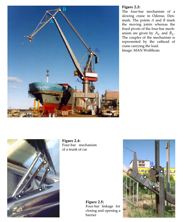
The planar motion of a rigid body can always be considered as an instantaneous rotation about a certain point. Since the hinges of the four-bar mechanism are forced to follow a circle path the
instantaneous center Ω is given by the intersection point of both cranks.

The tangent t to the coupler curve k is called "centrode tangent".
During the motion of the mechanism the instantaneous center of velocity changes continuously its position. The theorem of Etienne Bobillier (1798-1840) allows to determine graphically the direction vector (pole tangent ԏ) of the changing velocity u of the instantaneous center of rotation.

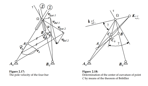
A proof of Bobillier's theorem can easily be achieved considering that the theorem of rotated velocities is valid. In applying Bobillier's theorem centers of curvature of arbitrary points in the moving plane can be sought as well.
The planar motion of a rigid body can alternatively be understood as a motion of rolling without slipping of the moving centrode on the fixed centrode . Suppose that the curves P and P0 are given. We consider now the body at two different moments of time t and t+dt. Ω represents the instantaneous center of velocity at a time t. After an infinitesimal period of time dt the center of velocity reaches the position Ω' . ω is the angular velocity of the rolling plane which changes with time as well.
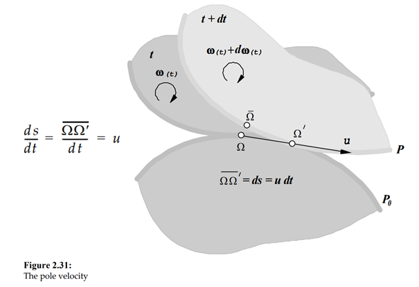
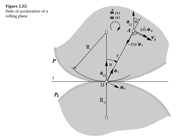
Figure 2.32 shows the state of acceleration of the moving plane rolling on the fixed centrode.
From this figure it is possible to derive the geometric locus of all points on the moving plane for which the value of the normal acceleration becomes zero. The derivation shows that the geometric locus is a circle, which is also called inflection circle. Both vectors the velocity and the acceleration vectors are parallel to each other and point into the same direction.

The geometric locus of all points for which the tangential acceleration becomes zero is also a circle which is the Bresse normal circle. The velocity vector is orthogonal to the acceleration vector. The acceleration pole Π is the point of intersection between the inflection circle and the Bresse normal circle, where the absolute acceleration of a point in the moving plane is instantaneously zero.

The theorem of Roberts:
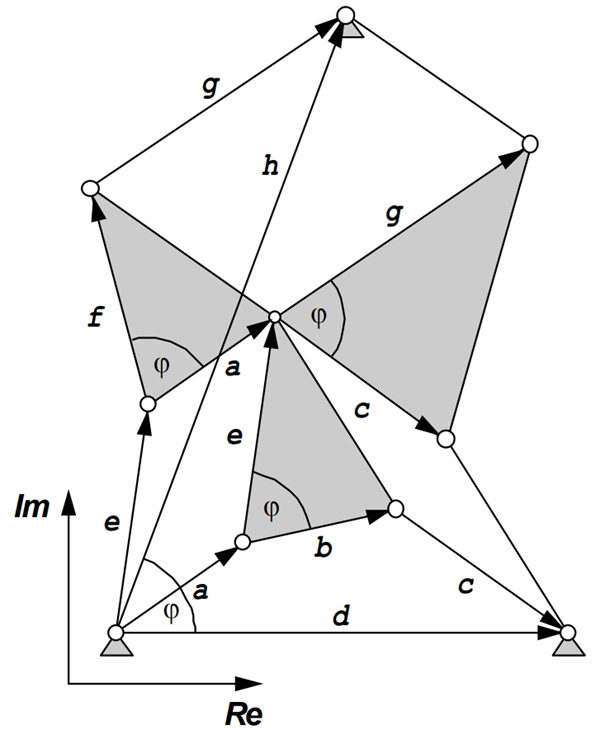
If an initial fourbar-mechanism is completed as the following figure shows, it can be proved by means of complex calculus that the vector h always remains constant. Therefore this point can be used as a pivot position for two additional and alternative four-bar mechanisms. As all three couplers are connected together all three mechanisms generate the same coupler curve.

The theorem of Roberts-Chebyshev can also be applied to the slider-crank mechanism.
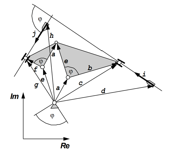
By means of complex calculus it is possible to deduce a relationship between the complex vectors d and h. We obtain the vector h after a rotation of vector d about the angle φ and an expansion of length by the factor of e/b.
The following figure shows the two existing cognates of the slider-crank mechanism. Either of them is usable to generate the same coupler curve.
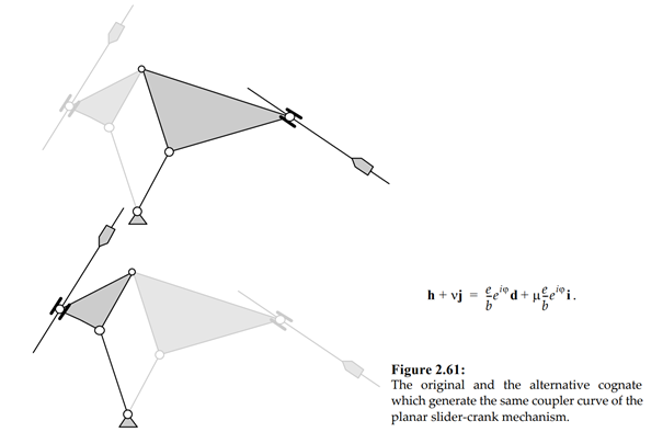
Both mechanisms which are built up of similar triangles and parallelograms in accordance with Roberts' theorem can alternatively be utilised as shape copying devices.

The cubic of stationary curvature is defined as the locus of all points in the coupler plane whose coupler points traverse instantaneously a vertex. Since the points A and B run through circular paths - as they are part of the cranks - they have to be located on the cubic of stationary curvature whereas the centerpoint curve which is the locus of all centers of curvatures of the cubic of stationary curvature must contain A0 and B0. Wherever the inflection circle intersects the cubic of stationary curvature, we obtain a geometric point whose path runs approximately along a straigth line. This point is called 'Ball's point', which is named after the Irish mathematician Sir Robert Stawell Ball (1840 - 1913). A variety of approximate straight-line mechanisms can therefore be found.
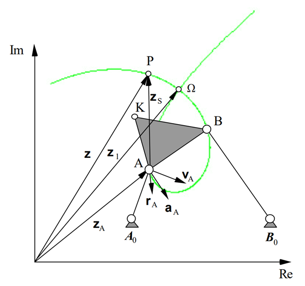
The figure shows the cubic of stationary curvature in green which has the shape of a loop.